


商品描述
商品属性
商品标签
相关商品
相关配件
购买过此商品的人还购买过
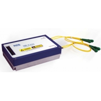
SERIES 5056D SELF-CONTAINED
HV SWITCHING MODULE Q-SWITCH DRIVER WITH ADJUSTABLE TIME DELAY
- 3 Nanosecond Output Rise time
- Single Shot to 5 kHz Repetition Rates
- EMI/RFI Shielded Enclosure
- 5 kV & 8 kV Output Voltage Models
- Works on +24 VDC Power Supply
- Integrated Front Panel Delay Control with 5 to 500 microsecond range
Model 5056D Q-switch Driver Modules integrate high voltage MOSFET circuits and Self-Contained miniature high voltage power supplies which require only +24 volts DC input. Trigger signals are TTL level voltages. The 5056D is intended for stand-alone operation with the company’s Series 1040, 1058, 1059, 1145, 1147 and 1150 electro-optic Q-switches operating at repetition rates between single-shot and 5 kHz. It will also drive similar KD*P, BBO, RTP & LiNbO3 Pockels cells from other manufacturers. All circuits are packaged in an electrically shielded enclosure which attenuates EMI/RFI to minimize radiated and conducted switching noise. The 5056D Input to Output Time Delay and Output Voltage are conveniently adjusted by a front panel mounted miniature potentiometers.
The 5056D features a balanced output, i.e., there are 2 independent output connections, one for each terminal on the Q-switch. The static, unswitched HV outputs have identical HV DC levels which produce a zero net differential voltage across the crystal.
Referring to the circuit diagram on page 2: when a trigger signal is applied, Side 1 switches from the pre-adjusted HV level to ground and then, between laser pulses, is allowed to recover to its original value.
Side 2 always remains at the original HV level so that during the time Side 1 is at the ground level ‘ON’ time, pre-set retardation voltage is applied to the crystal. The Q-switched pulse is generated during the ON time.
Given an appropriate Q-switch, the 5056D permits operation at the ¼ or ½ wave retardation voltages or at any voltage in this range. The 8,000 Volt Model 5056D-8 will produce pulsed voltages suitable for ½ wave retardation at 1064 nm with DKDP Q-switches and 1/4 wave retardation with BBO devices. Two other modes of operation are available without modifications: 1) capacitor coupled and 2) with DC HV voltage applied to the crystal.
5056D NOMINAL SPECIFICATIONS
Model 5056D-5
Model 5056D-8
Output Pulse Voltage Range, Volts
<1000 to 5000
<1000 to 8000
*Input to Output Delay Range, Adjustable
5 to 500 microseconds
Output Rise Time (Both models)
3 to 5 nanoseconds
[approx. 3 ns with <40 pf Total Load (cell+cable)]
Output Pulse ON Time
3 to 5 microseconds, typical
Jitter - Input to Output
<1 ns for both models
Repetition rate
Single Shot to 5 kHz
Input Trigger
TTL levels, 5 Volts max.
DC Power Input
+24 ± 5% VDC, 40 Watts max.
Panel Mounted Connectors: +24 VDC Power
BNC
Trigger Input (SMA to BNC cable provided)
SMA is standard, BNC available
**Output HV (SHV is standard)
SHV to RG59/u Shielded Cable - MHV available
Weight Approx.
1.5 kg
* Other Output Delay Ranges are available on request.
**Output cable set provided is 16 “ (41 cm ) long. Cable length should not exceed 3 feet (1 meter)
NOTES: The 5056D may be operated as a single ended driver. In this mode of operation, a DC high voltage is applied to the Pockels cell (PC) to attain a static ¼ or ½ wave retardation. The voltage may then be switched to the ground state. It will typically recover to the high voltage set point within 150 microsecond time period. This operation is set up as follows:
1. For units with SHV connectors: connect output 1 to a coaxial cable, typically RG59/U or RG62/U, and connect the center conductor and cable shield to the PC terminals. The PC crystal may exhibit residual birefringence and thus be sensitive to voltage polarity. It may be necessary to reverse these leads to attain the desired retardation with the lowest voltage. It is recommended that the center pin of connector
2 be taped over to prevent arcing between the center pin and the connector shell. 2. For units with insulated wire leads, connect the lead from side 1 to a terminal on the Pockels cell. The other cell terminal should be connected to ground. The lead from side 2 is not used but it must be well covered and insulated with electrical tape since it is not at zero voltage or ground potential. The 5056D enclosure should be grounded by connecting a wire lug to the 5056D mounting base and then wiring to house ground.


商品属性 [重复频率] Single Shot to 5 kHz

报价需求
返回顶部
© 2015-2024 神科仪购网/SNKOO-eGo 版权所有,并保留所有权利。
广州番禺区亚运大道1003号番山总部E谷3栋805 Tel: 020-84050812/13/16 ICP备案证书号:粤ICP备14034210号-1