
浏览历史
商品描述
商品属性
商品标签
相关商品
相关配件
购买过此商品的人还购买过
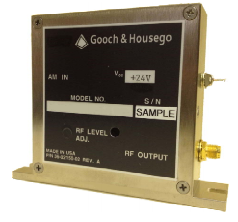
AOM Driver 3307 Series
1 to 4 Watt RF Drivers for Acousto-Optic Modulators
The 3307 Series RF driver provides up to 4 Watts output power. Various types cover a frequency range of 80 to 350 MHz.
The maximum RF output power is adjustable by an internal potentiometer.The driver is available in either analogue or digital modulation control. The analogue modulation voltage controls the output power from 0 to 100% of the adjusted maximum power. The digital modulation control signal can switch on and off the RF power.
The driver can be operated with modulation frequencies (analogue and digital) up to 25% of the carrier frequency and 50 MHz maximum at the higher carrier frequencies.
Optimum EMC shielding and mechanical protection is achieved by an aluminium casing. The base plate serves for mounting and heat dissipation purposes.
Many options are available with this driver including frequency tuning, automatic level control (ALC) and an external amplifier that can boost output power up to 20 Watts.
Key Features:
- Frequency range 80 to 350 MHz
- RF output power up to 4 Watt
- RF on/off ratio ≥ 35 dB (Digital Modulation)
- RF on/off ratio ≥ 35 dB (Analogue Modulation)
- Constant output power design
- Models with a modulation frequency up to 50 MHz available
- Conductive cooling through base plate
- Compact casing
Applications:
- Fast modulation components for extra cavity applications, e. g. laser
projection systems
- Frequency shifting
Technical Data
Supply Voltage
+24V DC, +28V DC
Supply Current
550 mA nom. with Pout = 0.35-1.5W@24V
550 mA nom. with Pout = 0.35-1.5W@28V
700 mA nom. with Pout = 2.0-4.0W@24V
700 mA nom. with Pout = 2.0-3.0W@28V (VI)
2000 mA nom. with Pout = 7.0W@24V (I)
2700 mA nom. with Pout = 20W@24V (I)
Output Impedance
50 Ω(nominal)
Maximum RF Power (adjustable)
< 0.1 W … > Pout
Frequency Accuracy
± 0.1%
Harmonic Distortion (II)
≤ -20 dBc
Analogue modulation
Impedance
Voltage range @ 50 Ω
RF ON / OFF ratio
50 Ω (nominal)
0 … +1 V (III)
≥ 35 dB (IV)
Digital modulation
Impedance
Level
RF ON / OFF ratio
50 Ω (nominal)
Standard TTL (V)
≥ 35 dB
RF Output Frequencies (IVII)
80, 110, 150, 200, 260 & 350 MHz
RF Rise/Fall Times
(Rise = 10% to 90%)
(Fall = 90% to 10%)
12 nsec @ 80 MHz
9 nsec @ 110 MHz
7 nsec @ 150 MHz
5 nsec @ 200 MHz
4 nsec @ 260 MHz
4 nsec @ 350 MHz
(I) 7W and 20W versions use an external amplifier.
(II) Into 50 Ω load
(III) Part numbers -52 and -58 are ≤ -30 dBc
(IV) Part number -40 is ≥ 42 dB
(V) Part numbers -12, -43 are (OFF: <+0.3V, ON:+1.0V)
(VI) Part numbers -03, -18, -22, -31, -44, -69: 550mA nom.
(VII) Other custom frequencies are available
connectors
RF output connector
SMA (female) (I)
Modulation connector
SMB (male) (II)
Frequency Tuning connector
SMC (male)
Reference Frequency connector
SMC (male)
ALC Connector
Input
Ground
Solder terminal (filtered feed-thru)
Solder lug
Power Supply connector
Input
Ground
Solder terminal (filtered feed-thru) (III)
Solder lug (III)
(I) Part number -12 & -43 have SMB (male)
(II) Part numbers -12, -29 & -43 have SMA (female)
(III) Part numbers -45 & -50 have Mini-Universal Mate-N-Lok connector
Frequency Tuning
Input Impedance
1 kΩ nominal
FM Bandwidth (3 dB)
90 kHz
Frequency Range
50 – 100 MHz
75 – 150 MHz
150 – 280 MHz
200 – 380 MHz
270 – 430 MHz
Input Voltage
+1.5 - +15 V nominal (I)
+1.5 - +15 V nominal (II)
+2.0 - +15 V nominal (III)
+1.0 - +15 V nominal (VI)
+2.5 - +12 V nominal (V)
(I) Part numbers -04, -25 and -68
(II) Part numbers -23, -49 and -59
(III) Part numbers -17, -28 and -48
(IV) Part numbers -62 and -63
(V) Part number -70
ALC (Auxiliary Level Control)
Input Impedance
1 kΩ nominal (I)
ALC Bandwidth
35 kHz nominal
RF Ouput (0 W – Full power)
+24 V (Vcc)
+28 V (Vcc)
+28 V (Vcc)
200 – 380 MHz
270 – 430 MHz
ALC Voltage level
0 – +21 V nominal
0 – +25 V nominal
0 – +5 V nominal (II)
0 – +10 V nominal (II)
(I) Part numbers -03, -10, -21, -22, -31, -38, -43, -69: 10KΩ
(II) Part numbers -03, -31, -38 and -43
(III) Part numbers -10, -21, -22 and -69
Reference Frequency
Output Reference Frequency
Fc divided by 256 (I)
(I) Part number -21
Cooling, Dimensions, Weight
Cooling
Pout
1.0 W - 1.5 W
2.5 W - 3.0 W
4.0 W
Conduction
Base plate should be attached to suitable heat sink capable of dissipating:
15 W
20 W
22 W
Dimensions inches [mm]L x W x H
4 x 1.12 x 3.15 [102 x 29 x 80]
Weight lbs [kg]
0.53 [0.24] (nominal)
Environmental Conditions
Warm-up Time
5 minutes (nominal)
Base Plate Temperature
0℃ to +60℃
For optimum output power stability constant base plate temperature should be provided
Storage Temperature
-25C to +85C (non condensing)
Absolute Maximum Ratings
Supply Voltage
+28 VDC
Analogue Modulation
-3.0 V to +3.0 V
Digital Modulation
-4.3 V to +4.3 V
Operating Temperature
+65C (base plate temperature)
Quality Standards
EU 2002/95/EC (RoHS)
Compliant
Burn-in
12 Hours min @ +25℃ and Pout
Outline Drawing:
(Dimensions in inches)

商品属性 [操作频率] 80 - 350 MHz [最大射频功率] 1-4 W [兼容的声光设备] Fiber-Q,Frequency Shifter

报价需求
返回顶部
© 2015-2024 神科仪购网/SNKOO-eGo 版权所有,并保留所有权利。
广州番禺区亚运大道1003号番山总部E谷3栋805 Tel: 020-84050812/13/16 ICP备案证书号:粤ICP备14034210号-1