
浏览历史
商品描述
商品属性
商品标签
相关商品
相关配件
购买过此商品的人还购买过
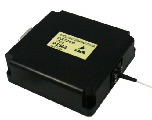
EM650 High Power DFB Laser Module
General Description
The EM650 integrates a high‐power fiber‐coupled DFB laser with both an ultra‐low noise laser current source and temperature controller. It represents a precision OEM solution for fiber coupled high power DFB lasers operating with excellent frequency stability, narrow linewidth, low noise, and stable polarization. The module contains a high‐power DFB laser, optical isola‐ tor, single‐mode fiber pigtail, thermo‐electric cooler, thermistor, and monitor detector integrated with a laser current source, temperature controller, and monitor detector readout amplifier. The entire module operates from a single +5 V supply. The unit provides a bi‐directional power adjust input that may be used for SBS prevention, for constant power operation in con‐ junction with the monitor detector readout signal and an external control loop, or for finely adjusting the laser oscillation frequency via chirp. The unit also incorporates a bi‐directional temperature adjust input for coarse tuning of the laser oscillation frequency. The module is designed and built using Gooch & Housego’s high‐ reliability platform for defense components and incorporates an advanced ultra‐low noise laser current source. The EM650 drives the internal TEC with a class AB linear H‐bridge and incorporates multiple layers of EMI pro‐ tection. It is G&H’s highest performance integrated laser solution and offers performance comparable to labor‐ atory equipment in a much smaller package.
Applications
· Long haul WDM transmission
· RF Links
· CATV
· Seeding
· Sensing
· Low‐noise High‐power Source
Features
· Integrated current source
· Integrated temperature controller
· Integrated monitor detector amplifier
· High optical output power
· ITU Wavelengths – Full C band coverage
· Low RIN
· Narrow Linewidth
· PM/SM fiber with or without furcation tubing
· Simple Interface
· Small form factor
· Operates from single +5V supply
Basic Operating Circuit
Ordering Information
The EM650 part number has the following structure:
EM650‐FFFFFF‐POW‐FIBUM‐CON‐NA
Valid values for each field are included at the end of this document.
Absolute Maximum Ratings
Stresses beyond those listed under “Absolute Maximum Ratings” may cause permanent damage to the device. These are stress ratings only and operation of the device at these or conditions beyond these is not implied. Exposure to absolute maximum ratings for extended periods of time may affect device reliability.
Parameter
Sym.
Condition
Min
Max
Unit
Storage Temperature
TSTG
non‐condensing atmosphere
‐40
+85
°C
Operating Temperature
TOP
temp. at base of module,
non‐condensing atmosphere
‐15
65
°C
Voltage Supply
VCC
4.7
5.5
V
Current Supply
ICC
3.5
A
Laser Enable Input Voltage
LE
GND‐0.3
VCC +0.3
V
Laser Enable Input Current
ILE
2
mA
Power Adjust Input Voltage
Vpa
Warning: see notes
0
2.6
V
Power Adjust Input Current
Source or Sink
Warning: see notes
‐3.5
3.5
mA
Temperature Adjust Input Voltage
Vta
Warning: see notes
0
5
V
Temperature Adjust Input Current
Source or Sink
Warning: see notes
‐3.5
3.5
mA
Monitor Detector Output Voltage
VMON
VCC
V
Monitor Detector Output Current
Source or Sink
IMON
‐15
15
mA
Optical Output Power
Pop
110
mW
Optical Characteristics
TOP=25°C unless otherwise noted, All parameters measured after an initial 60s settling time. VCC = LE = 5.0V with PA and TA open.
Parameter
Sym.
Condition
Min
Typ
Max
Unit
Optical Output Power Setpoint
POP
See ordering information
Pop
mW
Optical Output Power Fluctuation1
△POP
1σ, tm=400s,0.1s avg&period
20
50
PPM
Long‐Term Power Fluctuation
△POP
1σ, tm=20hr,0.1s avg, 18s period
200
500
PPM
Temperature Drift
△PT
‐10 ≤ TOP ≤ 60°
500
PPM/°C
Optical Frequency Accuracy2
FOP
‐5
+5
GHz
Optical Frequency Stability3
△FOP
See note 3
<20
MHz
Temperature Dependent Frequency Drift
△FT
‐10 ≤ TOP ≤ 60°
±200
MHz/°C
Side Mode Suppression Ratio
SMSR
30
dB
Polarization Extinction Ratio
w/ PM fiber only
17
20
dB
Optical Isolation
30
35
dB
Linewidth
△ν
170
kHz
Relative Intensity Noise4
RIN
50 MHz to 18GHz
‐155
‐150
dBc/Hz
Cold Start Settling Time
VCC=VEN 0®5V
30
s
Rise Time (Hot Start)
tR
VEN=0®5V
30
ms
Fall Time (Hot Standby)
tF
VEN=5®0V
5
µs
Back Facet Tracking Over Temp
‐10
+10
%
Electrical Characteristics
Parameter
Sym.
Condition
Min
Typ
Max
Unit
Voltage Supply
Vcc
across inputs
5
V
Current Supply
Icc
3
A
Laser Enable High
LEH
3.5
V
Laser Enable Low
LEL
1.5
V
Laser Enable Input Impedance
ZLE
5
kW
Power Adjust4
Vpa
Warning: see notes
0
2.2
V
Power Adjust Input Impedance
ZPA
to 2V Vref
1
kW
Power Adjust Bandwidth
‐3dB
8
kHz
Temperature Adjust
Vta
Warning: see notes
1.5
3.5
V
Temp Adjust Input Impedance
Zta
to 2.5V Vref
1
kW
Monitor Detector Output
VMON
at Pop
1
3
V
Environmental Characteristics
Parameter
Sym.
Condition
Min
Typ
Max
Unit
Storage Temperature
Tstg
non‐condensing
‐40
+85
°C
Operational Temperature
Top
temp. at base of module,non‐condensing
‐10
+60
°C
Electrical Connector
Pin
Name
Description
1
VCC
Voltage supply
2
VCC
Voltage supply
3
GND
Ground connection
4
GND
Ground connection
5
GND
Ground connection
6
TA
Temperature Adjust Input
7
Vmon
Monitor Voltage Output
8
LE
Laser Enable
9
PA
Power Adjust Input
Shield
Connected to connector shield only
Mating Connector
DB‐09F, Standard DB‐09 Female/Receptacle/Socket Connector
Optical Fiber Specification
Parameter
Type
Unit
Fiber Type
Single‐mode PM or non‐PM
‐
Core Diameter
8
µm
Outer Diameter
125
µm
Buffer Diameter
250 (optional 900 μm loose buffer avail.)
µm
Buffer Material
Acrylate (optional loose‐buffer is PVDF)
‐
Minimum Length
1
m
Minimum Bend Radius
35
mm
Connector Type
FC or SC/APC, key parallel to slow axis; key type is tight‐fit/narrow
‐
Output Polarization
Parallel to slow axis
‐
Mechanical Drawing
Typical Operating Characteristics (80 mW Module)
Typical Operating Characteristics (continued)
1 Power stability of this magnitude is strongly influenced by any movement of the fiber. To duplicate this stability measure‐ ment the fiber must be secured and motionless.
2 For 228.849 THz (1310 nm) lasers the laser frequency tolerance is ±1.750 THz (±10 nm).
3 Frequency stability measured by heterodyne of two free running EM650 units over 100s.
4 The peak of the RIN curve corresponds to the relaxation oscillation frequency of the laser which varies in proportion to the drive current above threshold by frelax α ((Ild/Ithreshold) ‐ 1)1/2. Customers employing this device in RIN sensitive applications should therefore be aware that reducing power using the PA input will reduce performance.
DFB Laser Modules EM650 1529-1610 nm 040,050,063,080,100 DFB MODULE PM Low Linewidth DFB Laser Modules, 1064 EM650 1064 nm 50 mW DFB MODULE PM 1064 nm DFB Laser Modules, 1310 EM650 1310 nm 18 mW DFB MODULE PM 1310 nm


商品属性 [波长] 1529 thru 1610 nm [功率] 040,050,063,080,100mW

报价需求
返回顶部
© 2015-2024 神科仪购网/SNKOO-eGo 版权所有,并保留所有权利。
广州番禺区亚运大道1003号番山总部E谷3栋805 Tel: 020-84050812/13/16 ICP备案证书号:粤ICP备14034210号-1