

商品描述
商品属性
商品标签
相关商品
相关配件
购买过此商品的人还购买过
Optical Delay Line | Products Line
Applications:
Key features:
Radar Calibration & Testing
Delays: 0.1-300 μsec (fixed)
Signal & Phase Noise Processing
Frequency Range: L, S, C, X and Ku radar bands (0.1-20GHz) ODL versions
Extension of radar range site
Delay accuracy: 1%
Clutter Canceler
Remote Control: RS-232 or Ethernet
BIT (built-in test)
High Dynamic Range
EW Systems - Jammers
Variety of configurations
Path Delay Simulation
Up to 15 usec can be housed in Mini enclosure
Options:
ODL with 2, 4, up to 8 switchable delays
Delay accuracy of 0.1 % (not less then 25 nsec)
RF Bypass
Dispersion Compensator for long delay line
Various Gain
Control RS-232 or TTL or Ethernet
Full BIT using signal detection at the receiver
RFOptic's optical delay line ODL series provides a high performance solution for testing and calibration of radar systems, or for RF communication. The ODL converts analog RF signals in the 0.1-20 GHz range to optical signals and back. The RF input signal is converted into an optical modulated signal, which is then transmitted into a single mode fiber, creating a fixed time delay defined by the fiber length. After passing the fiber, the optical signal is converted back into an electrical RF signal, which is identical to the input RF signal. Any fixed time delay between 0.1 and 300 μsec can be provided to customers.
The ODL is operated as a standalone unit with no need for any intervention by the operator - it can be also controlled externally from a PC through various communication interfaces.
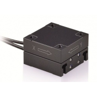
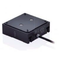
RFOptic's ODL unit is a compact solution, which provides superb performance including accurate time delay and with ultra silent operation. The ODL can be purchased with an integral switch unit supporting up to 8 predefined time delay values in a single ODL unit.
For some applications, RFOptic offers low cost ODL solution up to 5GHz based on direct modulation.
Table below describes the typical specifications ODL
Parameter
Unit
Specifications
Note
RF
Frequency range [1]
GHz
L,C,S,X,Ku
Delay time [2,3,4,5]
µsec
0.1-300
pre-fixed delay defined by customer
Delay accuracy [6]
%
1
Minimum accuracy of 25 ns
Delay repeatability
%
<0.01
at +/- 5 ℃ variations
System RF gain [7,8]
dB
-30
Without the Delay Line loss
Noise Figure at 10GHz [7]
dB
40
Without the Delay Line loss
Group Delay Variation
psec
± 100
1dB input Compression point
dBm
> 15
Max input RF power
dBm
+23
Spurious [9]
dBc
<-100
Phase noise (at 10kHz offset)
dBc
<-100
RF Flatness (not including amplifier) [10]
dB
± 2.0 | 2.5 | 3.0
for 0.1 - 8 | 15 | 18 GHz Bands
VSWR
-
2:1
Impedance
Ohm
50
Mechanical
1550 nm laser CW optical power
mW
≤ 20
Communication [11]
-
RS-232
RF connectors
-
SMA
N type is available
Main AC supply
VAC
220/110
DC version is available
19” Rack mounting [12]
mm3
440 x 450 x 133
See mechanical drawing
Operating Temperature
℃
-20 ÷ +60
Storage
℃
(-40) ÷ +85
(1) L, S, C, X, Ku versions are optional.
(2) Any fixed delay between 0.1 to 300 µsec is optional.
(3) Integrated switching unit allowing choosing between 2 to 8 predefined delay values is optional.
(4) RF bypass is optional.
(5) Dispersion compensator unit for long delay / high frequency is optional.
(6) 0.1% accuracy for long delay line is optional.
(7) Not including delay line loss which is about 1dB per 10 µsec delay and optical switches loss.
(8) Pre-Amp may be added to improve the noise figure by about 15dB. Post-Amp may be added to improve the system ODL system gain.
(9) Excluding in-band harmonics.
(10) Additional ±0.5 dB deviation is considered within spec.
(11) TTL or Ethernet are optional.
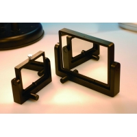
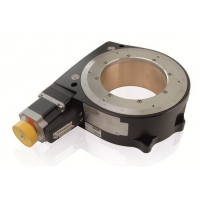
(12) Variety of ODL enclosures are optional.
(13) Full BIT is optional (using signal detection at the receiver).
(14) 20GHz ODL is optional.
Mechanical Layout: 2U/3U Layout
Note: 3U is similar with 133 mm height.
Comment: An option for up to 8 ports rear panel for external delay line.


报价需求
返回顶部
© 2015-2024 神科仪购网/SNKOO-eGo 版权所有,并保留所有权利。
广州番禺区亚运大道1003号番山总部E谷3栋805 Tel: 020-84050812/13/16 ICP备案证书号:粤ICP备14034210号-1