

商品描述
商品属性
商品标签
相关商品
相关配件
购买过此商品的人还购买过
Variable Gain Sub Femto Ampere Current Amplifier DDPCA-300
Features
0.4 fA peak-to-peak noise
Transimpedance gain from 104 to 1013 V/A
240 dB dynamic range for sub-fA to mA measurements
Adjustable voltage on input for DUT biasing
Compact housing for use close to the signal source
Manual and remote control
Sub Femto Ampere Sensitivity
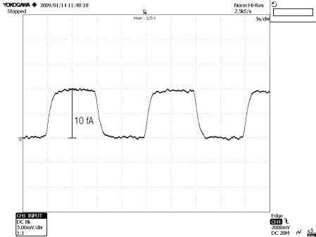
The variable gain sub femto ampere amplifier DDPCA-300 is the latest addition to FEMTO's broad range of low noise transimpedance amplifiers. Its exceptional design achieves input noise values down to 0.2 fA/√Hz and 0.4 fA peak-to-peak. The gain can be set over a very wide range from 104 up to 1013 V/A either manually or by a remote interface. Thus, the amplifier covers a large dynamic range of more than 240 dB for the measurement of currents from sub femto amps up to milli amps by simply switching the gain range. The compact housing is optimized for use close to the signal source avoiding signal perturbations or noise pick-up due to long cables. Various filters are integrated to adapt the amplifier bandwidth to varying signal conditions. Thus, the signal to noise ratio and measurement speed can be optimized by selecting the proper filter setting for a specific application. And even in the highest gain settings the measurement speed is sufficient to measure femto amp currents in real-time without the need for external averaging or long test periods (see figure 1 below).
Low Drift for Stable Long-Term Performance
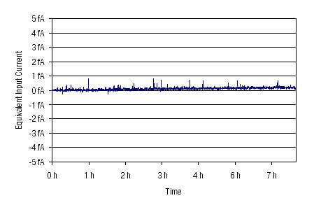
At the femto ampere level drift and offset currents can easily cause measurement errors and shifting baselines. The design of the DDPCA-300 is optimized for long-term stability and extremely low drift. The below figure shows the amplifier's baseline drift of less than 0.5 fA measured over a period of more than 7 hours. In case of inevitable (e.g. temperature related) offsets an trimpot is provided for cancelling unwanted offset currents and for nulling of the baseline.
Device characterization by source Biasing
The very high sensitivity of the DDPCA-300 can be utilized in low current applications like characterization of high resistance semiconductors (e.g. MOS or JFETs) or quantum-dot devices. An adjustable voltage is supplied directly at the amplifier input for biasing the device under test (DUT). Changing the bias voltage manually or through the remote interface in the range of ±10 V allows the characterization of the DUT for different bias voltages in spectroscopic measurements. For applications not requiring a bias voltage like photocurrent measurements or beam monitoring in particle physics the bias voltage can be easily disabled.
Applications
Photo and ionization detector amplifier
I/V characterization of MOS and JFET structures
DC measurement of ultra-low currents
Quantum and biotech experiments
Spectroscopy
High resistance measurements
Easy-to-use FEMTO amp add-on to existing digital voltmeter or A/D converter
Model
DDPCA-300
Transimpedance [V/A]
104
105
106
107
108
109
1010
1011
1012
1013
Bandwidth* (-3 dB) [Hz]
400
400
400
400
150
150
20
20
1
1
Rise Time* (10 % - 90 %) [ms]
0.8
0.8
0.8
0.8
2.3
2.3
17
17
350
350
Integrated Input Noise* (Peak-Peak)
7 nA
7 nA
70 pA
70 pA
1.2 pA
1.2 pA
50 fA
50 fA
2 fA
2 fA
Spectral Input Noise Density [/√Hz]
45 pA
45 pA
0.5 pA
0.5 pA
15 fA
15 fA
1.3 fA
1.3 fA
0.2 fA
0.2 fA
Accuracy Performance
Gain ±1 %
Adjustable Low Pass Filter
3 settings: full bandwidth, 0.7 Hz and 0.1 Hz
Output Performance
±10 V, ±30 mA
Bias Voltage
±10 V, max. 10 mA, connected to amplifier input, adjustable by trimpot or remote control voltage
Power Supply
±15 V, +70 mA / -15 mA typ., ±150 mA recommended
Control Interface
4 opto-isolated digital inputs, TTL/CMOS compatible, analog bias control voltage input
Case
170 x 60 x 45 mm (L x W x H), Weight 320 g (0.74 lb.)
* The values for bandwidth, rise time and integrated input noise stated in the table above are achieved with the low pass filter set to full bandwidth. Lower peak-to-peak noise values can be achieved by setting the low pass filter to 0.7 Hz or 0.1 Hz. The minimum peak-to-peak noise of 0.4 fA is achieved in the gain settings 1012 and 1013 V/A with the low pass filter set to 0.1 Hz.
Offset adjustable by trimpot. Overload indication by LED and digital control output. Input protected against ±2 kV transients. Output short-circuit protected. Power supply via 3-pin Lemo® socket. A mating connector is provided with the device. Optional power supply PS-15 available.
Figure 1: Femto Ampere Measurements in Real-Time without Averaging
Figure 2: Long Term Drift
商品属性 [频率] 1-400Hz [互导倒数] 104 to 1013 V/A [上升时间] 0.8-350ms [集成输入噪声] 7nfA-2fA [光谱输入噪声密度] 0.2fA-45pA

报价需求
返回顶部
© 2015-2024 神科仪购网/SNKOO-eGo 版权所有,并保留所有权利。
广州番禺区亚运大道1003号番山总部E谷3栋805 Tel: 020-84050812/13/16 ICP备案证书号:粤ICP备14034210号-1