
浏览历史

商品描述
商品属性
商品标签
相关商品
相关配件
购买过此商品的人还购买过
2x8 Coherent Mixer with Single-ended Photodetectors
Description
This page defines the requirement of a special coherent receiver with 8 single-ended photodiode outputs, per customer request.
The coherent mixer, consisting of two polarization-diversified 90deg optical hybrids, a polarizing beam splitter and a beam splitter, is exactly same as existing DP-QPSK coherent mixer, and therefore offering same optical performance.
Figure 1, Optoplex’s existing 2x8 DP-QPSK Coherent Mixer
To achieve the required configuration, functionalities and performance, 8 individual single-ended photodiodes are used to replace the 8 output collimators in the existing coherent mixer design.
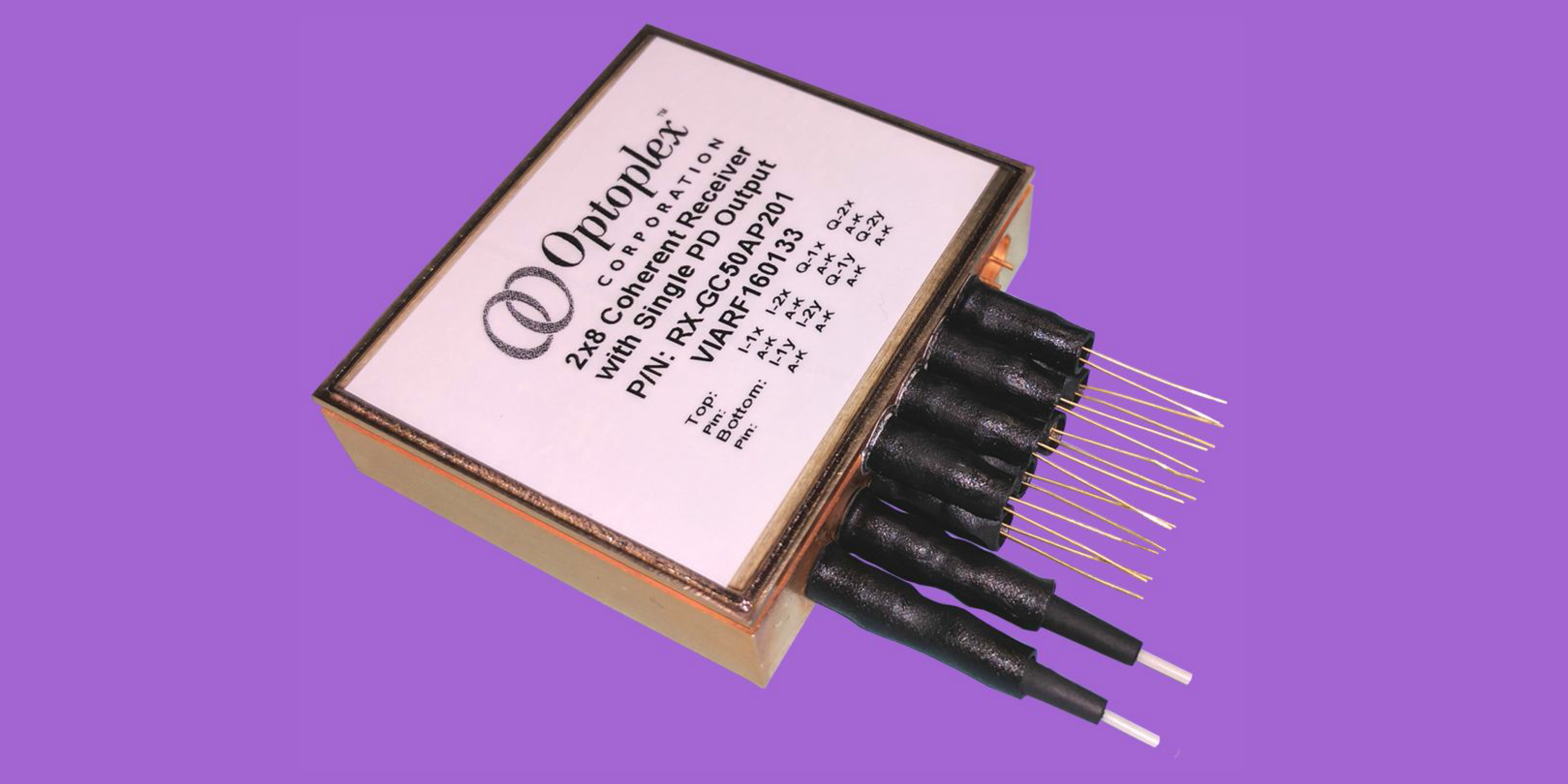
Figure 2, Optoplex 2x8 coherent receiver with 8 single-ended PD outputs
Figure 3, Functional block diagram of the coherent receiver with single-ended PD output
The 8 single-ended photodiodes are completely independent of each other – each one has its own and separate ground to provide the user the flexibility for independent monitoring and control.
Features and Benefits of 2x8 Coherent Mixer with Single-ended PDs
Free-space optics based 90deg optical hybrid
Accurate 90deg phase difference, small temperature, wavelength and
polarization dependence
Superior optical performance (IL, TDL, PDL, Skew, etc.)
Low dark current
High CMRR
High PER
Applications of 2x8 Coherent Mixer with Single-ended PDs
Coherent Doppler LIDAR system
Coherent detection in fiber sensing
Coherent detection in OCT and other biomedical sensing/imaging systems
Coherent spectroscopy instrumentation
Coherent detection in optical communications
Optical Performance Specifications of 2x8 Coherent Mixer with Single-ended PDs
Parameter
Min
Typ.
Max
Unit
Conditions
Operating Wavelength Range
1525
1568
nm
C-Band
Tributary path delay
-
20
ps
Maximum skew between any path (XI, XQ, YI and YQ), Note 1
Tributary path delay variation
5
ps
Skew variation over operating conditions and aging
P/N path delay imbalance
-
2
ps
Between balanced pairs, over operating conditions and aging
Phase angle error
-5
+5
degree
Deviation from 90° angle between I and Q
Polarization extinction ratio
20
dB
To be measured over photocurrents
Optical return loss
27
dB
Each input
Responsivity of individual tributaries2
45
mA/W
Responsivity variation of individual tributaries over temperature
1.0
dB
Over operating case temperature range
P/N Responsivity imbalance3
0.85
dB
For Signal and LO path
Responsivity imbalance between tributaries 4
1.0
dB
Notes:
Overall delay between signal input or LO input and the respective electrical output. TIA gain set to medium gain. Use a heterodyne measurement setup. Sweep the beat frequency from 0.1 – 10 GHz and derive the phase response between any path (XI, XQ, YI, and YQ).
This is the worst case responsivity of one individual tributary from LO or Signal input, to one of four outputs, thus including inherent and excess loss. The responsivity is to be averaged over the P and N components of each tributary. To measure the average responsivity of the Signal path, a polarization scrambled signal shall be used.
Imbalance between P/N pair of one tributary for Signal and LO path. The imbalance is related to CMRR_DC. The definition of CMRR_DC is:
4.Imbalance between XI, XQ, YI, YQ channels, for signal and LO path. The individual tributary’s P/N responsivity has to be averaged.


商品属性 [波长] 1525-1568nm

报价需求
返回顶部
© 2015-2024 神科仪购网/SNKOO-eGo 版权所有,并保留所有权利。
广州番禺区亚运大道1003号番山总部E谷3栋805 Tel: 020-84050812/13/16 ICP备案证书号:粤ICP备14034210号-1